
Your PC isn’t turning on, before you assume something expensive broke, understand this: the overwhelming majority of no-power situations are caused by something simple. A loose cable. A switch in the wrong positio, a RAM stick that needs reseating. These causes account for roughly 90% of all reported PC power failures, and every one of them costs nothing to fix.
Work through this pc won’t turn on guide in order, the steps are arranged from most common to least common cause, most people find their problem in the first four steps.
Before anything else: the three checks that take ten seconds each
Check the PSU power switch. On the back of your PC, the power supply has its own rocker switch marked with a circle (off) and a line (on). It defaults to off when a new PSU ships. If someone knocked it, bumped it, or if this is a new build, it may be in the off position. Flip it to the line (on) position.
Check the wall outlet, plug a lamp or phone charger into the same outlet. If it works, the outlet is fine, if not, try a different outlet. A dead outlet or tripped surge protector is surprisingly common.
Check the power cable, unplug the cable from the back of the PSU and from the wall, then reconnect both firmly. Power cables can look connected while being slightly unseated.
If none of these resolve it, move to the systematic diagnosis below.
Understanding what symptoms tell you
The symptoms you see or don’t see narrow down the likely cause before you open the case.
Nothing happens at all , no fans, no lights, no sound when you press the power button, this points to a power delivery problem: the PSU isn’t receiving power, the PSU itself has failed, or the power button signal isn’t reaching the motherboard.
Fans spin for a moment then stop , the system starts to power on then immediately shuts down. This usually indicates a short circuit somewhere, a failed component that the PSU protection circuitry is detecting, or a CPU that isn’t seated correctly.
Fans spin continuously but no display , the system is running but not completing POST. This points to RAM, GPU, or display connection issues rather than a power problem.
Power LED on but system appears dead , the motherboard has standby power but isn’t booting. Could be a failed component, corrupted BIOS, or a POST failure the system can’t recover from.
Work through the relevant sections below based on your symptoms.
Step 1: Check the 24-pin and 8-pin power connections
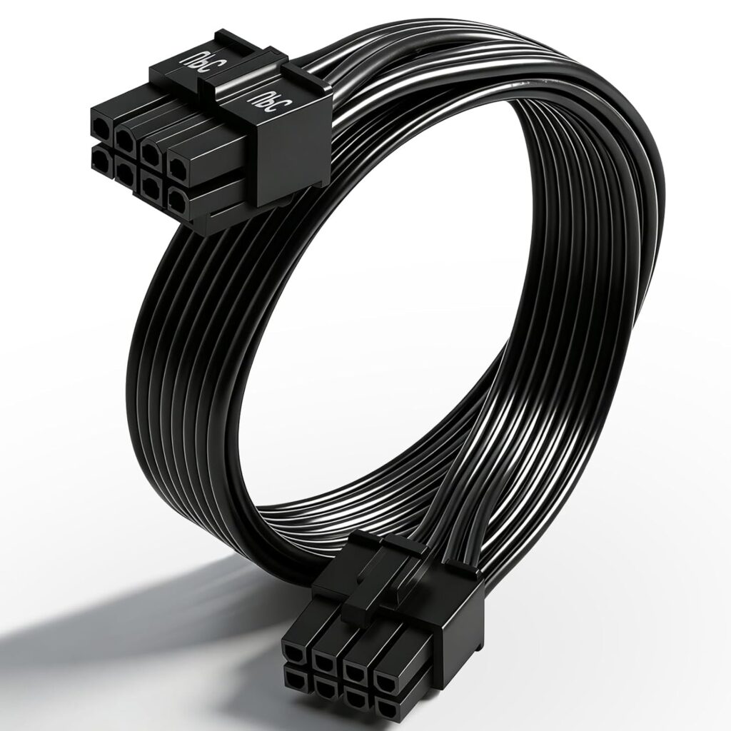
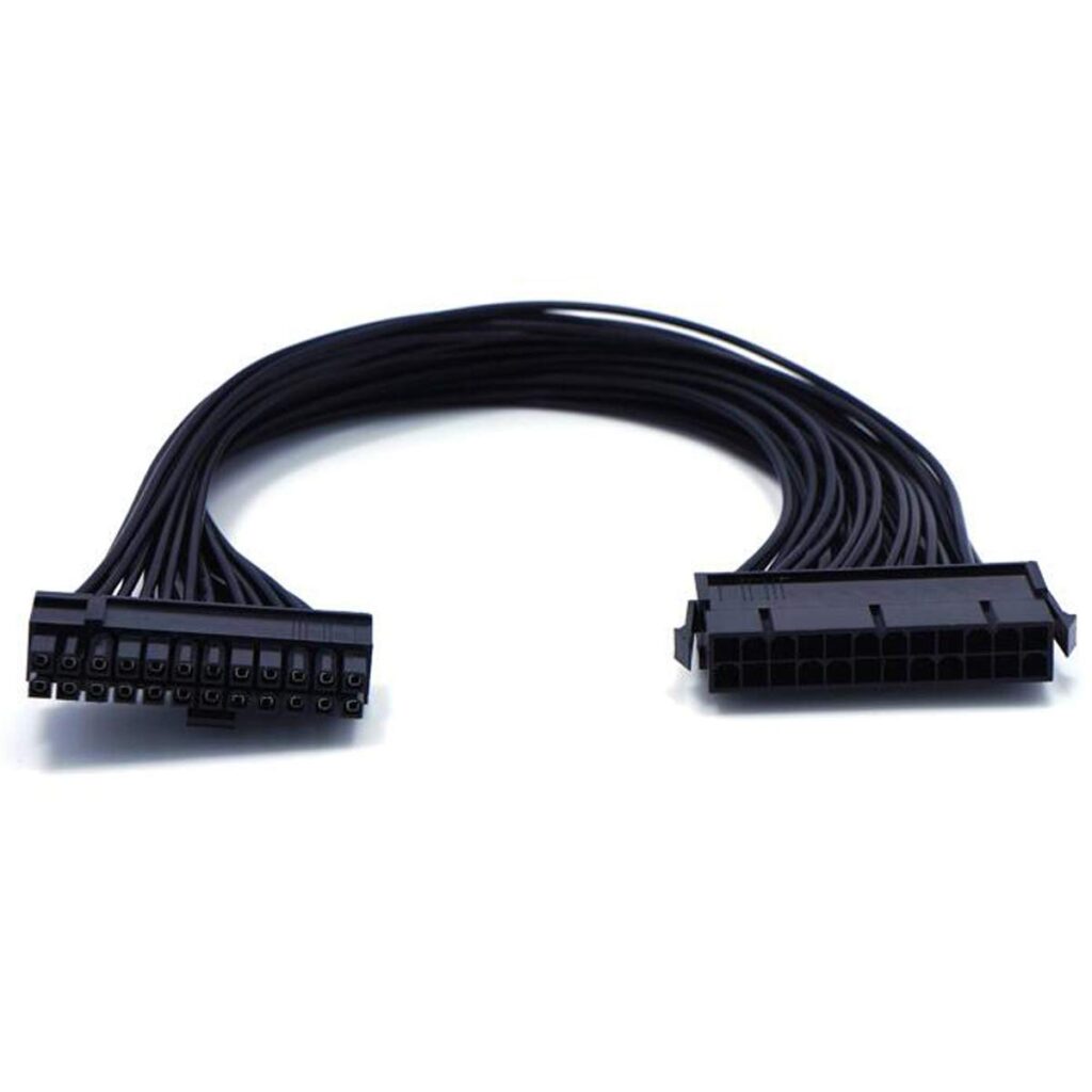
The two most frequently loose connections in any PC build are the 24-pin ATX power connector (the large cable that runs from the PSU to the motherboard) and the 8-pin CPU power connector (the smaller square connector near the top of the motherboard, sometimes labelled EPS12V or CPU).
The 24-pin connector should click audibly when seated. Run your finger along the side there’s a locking tab that should be fully engaged, wiggle the connector slightly if it moves, it isn’t seated.
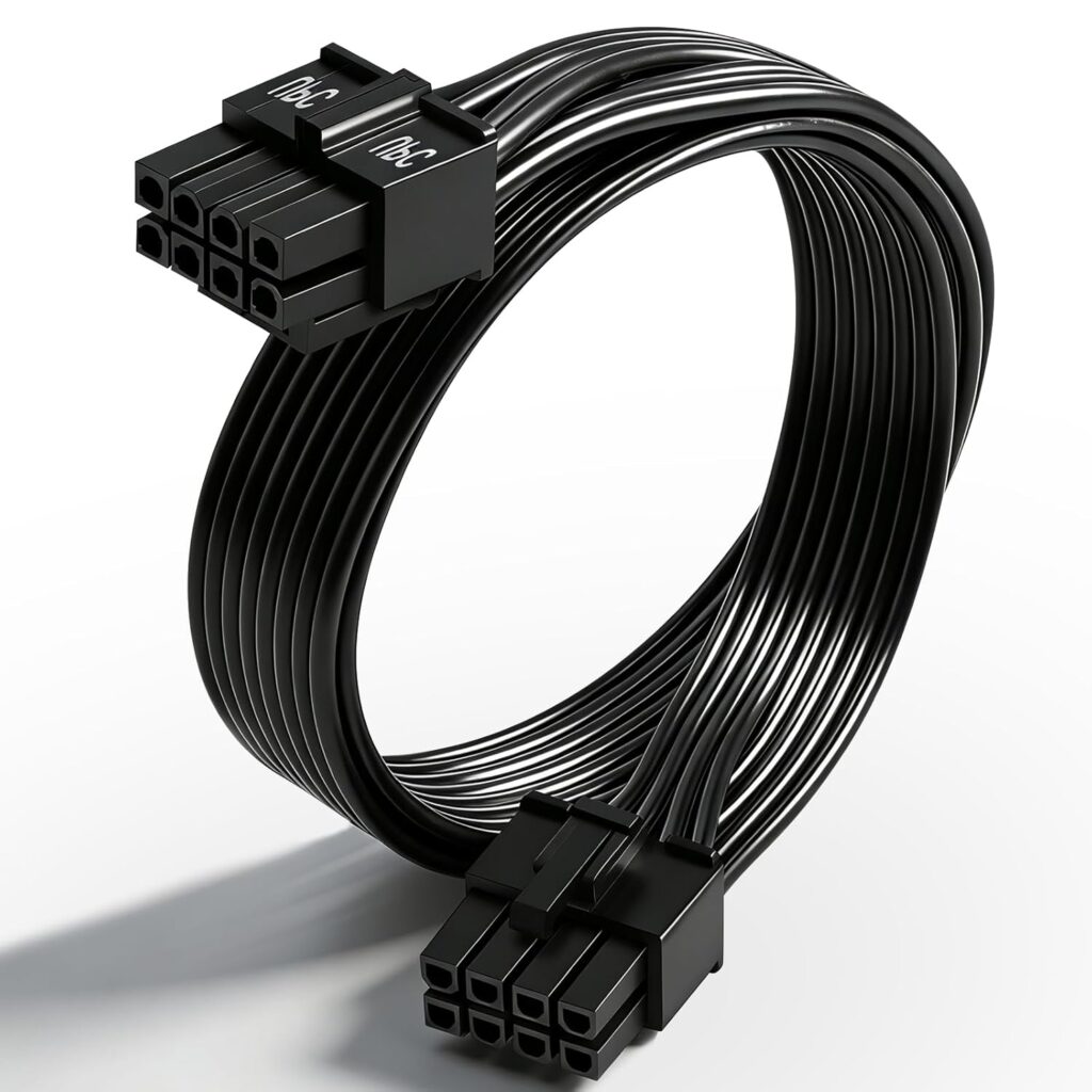
The 8-pin CPU power connector is the one builders most frequently forget on new builds. It’s located away from the main motherboard connector, often in the top-left corner of the board, and it’s easy to miss in cable routing. A system with the 24-pin connected but the 8-pin missing typically shows fans spinning briefly then shutting down, or fans spinning with no POST.
On some high-end builds the CPU power connector is a 4+4 pin configuration two groups of four that connect together. Ensure both halves are connected to the motherboard header.
Unplug and firmly reconnect both connectors, then try powering on again.
Step 2: Reseat the RAM
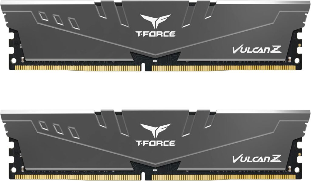
RAM is the single most common cause of no-POST symptoms fans spin, system appears to be running, but nothing appears on screen. It’s also the most common cause of complete no-power symptoms on new builds where the builder didn’t seat the sticks firmly enough.
Power down completely, unplug from the wall. Press the power button once to discharge residual current. Remove the side panel. If you end up reseating the memory, our guide on how to install RAM shows the right slots.
Press the retention clips on your RAM slots outward to release. Remove both sticks. Look at the gold contacts they should be clean and undamaged. Reinsert each stick firmly with even pressure on both ends until both retention clips click into place. The force required is more than most beginners expect.
If you have two sticks, try booting with only one stick in slot A2 (the second slot from the CPU on most boards). If it boots, add the second stick and try again. This isolates whether one stick is faulty.
Reconnect power and try again.
Step 3: Check the front panel power button connector
The power button on your case connects to the motherboard via a two-pin header a small cable labelled PWR SW or POWER SW that plugs into a header block on the motherboard typically labelled F_PANEL or JFRONT.
If this connector is loose, plugged into the wrong pins, or plugged in with reversed polarity (the power button is not polarity-sensitive but the connector can sometimes be seated on the wrong pin group entirely), pressing the power button does nothing the signal never reaches the motherboard.
Find the front panel header block on your motherboard check the manual for its location if you can’t find it. Confirm the PWR SW connector is on the correct pins. On most boards this is clearly labelled. Remove and reinsert the connector firmly. If the problem started after a CPU swap, recheck the seating with our guide on how to install a CPU.
As a test: once the connector is confirmed, you can also short the two power button pins on the motherboard header directly with a flat-head screwdriver bridge both pins briefly. This bypasses the case power button entirely and triggers the power on signal. If the system starts with the screwdriver short but not the button, the case power button or its cable is faulty.
Step 4: Check GPU seating and PCIe power
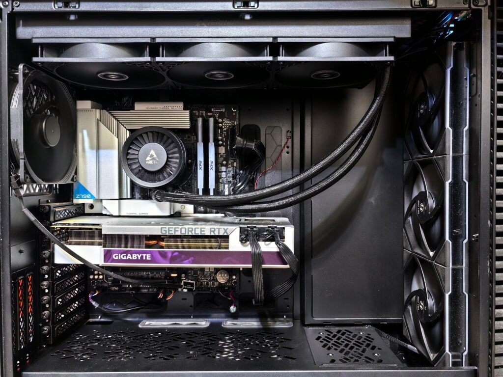
If your symptoms are fans spinning with no display, the GPU is the next check.
Press the PCIe retention clip on the motherboard slot it’s a small tab at the end of the GPU’s PCIe slot. Remove the GPU completely, check the gold contacts on the PCIe connector for dust or debris. Reseat the GPU firmly it requires more downward force than most builders use, and the PCIe retention clip should click when the card is fully seated.
Check the PCIe power connectors on the GPU itself, RTX 50 series cards use the 16-pin 12V-2×6 connector. RTX 40 and 30 series use 8-pin connectors, sometimes two or three of them. Ensure every power connector on the GPU is fully seated a GPU with one of two power connectors unplugged will either not power on or will produce a warning beep.
One common mistake on new RTX 50 series builds: the 12V-2×6 connector has a specific insertion direction and requires firm pressure to seat. A partially connected 16-pin connector looks connected but isn’t. Push until you feel the connector click into the GPU socket.
If you have integrated graphics on your CPU Intel Core Ultra chips have integrated Xe graphics, some AMD Ryzen chips with G suffix have integrated Radeon graphics try removing the discrete GPU and connecting your monitor to the motherboard’s video output. If the system posts with integrated graphics, the discrete GPU may be the faulty component.
Step 5: Clear the CMOS
A corrupted BIOS configuration can prevent the system from posting. Clearing CMOS resets all BIOS settings to factory defaults including any overclocks, XMP profiles, or custom configurations but solves POST failures caused by bad BIOS settings.
Every motherboard has a CMOS clear button or jumper. Modern boards often have a dedicated CLEAR CMOS button on the rear I/O panel a small button labelled CLR CMOS or similar. Press and hold it for five seconds with the system powered off and unplugged.
If no button is present, the motherboard manual will show a CMOS clear jumper typically two or three pins labelled JBAT or CLR_CMOS. Short the appropriate pins with a screwdriver for five seconds or move the jumper cap to the clear position, wait five seconds, and return it to normal position.
After clearing CMOS, reconnect power and try booting. If the system posts, you’ll enter BIOS setup to re-enable XMP/EXPO and any other settings. Re-enabling a previously stable XMP profile that caused POST failure suggests the RAM kit isn’t fully compatible with your motherboard at its rated speed try a lower XMP profile or enable EXPO at a reduced frequency.
Step 6: Test with minimum hardware
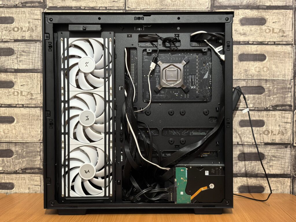
Strip the build to its absolute minimum: one RAM stick in slot A2, no GPU (if you have integrated graphics), no drives, no USB devices connected. Remove any PCIe cards other than the GPU. Disconnect any additional case fans beyond what’s required.
If the system posts with minimum hardware, add components back one at a time GPU, then drives, then additional cards. The component that causes the failure when added is the faulty or conflicting part.
This process is tedious but definitive, a system that won’t post with minimum hardware has a problem with one of: the PSU, motherboard, CPU, or the single RAM stick you’re testing with. Swap each in sequence with known working alternatives to isolate the fault.
Step 7: The PSU paperclip test
If you suspect the PSU is dead, you can test it independently without a motherboard. This is the paperclip test it bypasses the motherboard’s power-on signal to confirm whether the PSU itself is functional.
Unplug the PSU from everything, take the 24-pin ATX connector. Find pin 15 the green PS_ON wire and pin 17 any black ground wire. Short these two pins together with a piece of wire or a bent paperclip. Plug the PSU back into the wall and flip its switch on.
If the PSU fans spin, the PSU is receiving power and can deliver it, if nothing happens, the PSU is dead. This test doesn’t confirm the PSU is delivering correct voltages a PSU that spins its fan but delivers wrong voltages can still cause boot failures but it confirms whether the unit has basic functionality.
A failed PSU is more common than most builders expect. Quality PSUs last five to ten years but can fail earlier under sustained high load. If your system suddenly stopped working after working correctly, and all other components check out, the PSU is the most likely culprit.
Step 8: Motherboard diagnostic LEDs and beep codes
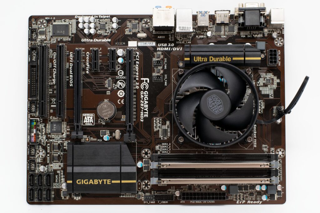
Most modern motherboards have diagnostic LEDs near the 24-pin connector or along the board edge typically labelled CPU, DRAM, VGA, and BOOT. These light up in sequence during POST and stay illuminated at the point where POST fails.
A DRAM LED staying on indicates RAM failure or incompatibility. A CPU LED indicates CPU or power delivery failure. A VGA LED points to GPU. A BOOT LED suggests the system is reaching the point of looking for a boot device but failing check storage connections and BIOS boot order.
Some older motherboards produce beep codes through a motherboard speaker. The pattern of beeps corresponds to specific POST failure codes documented in the motherboard manual. If your board has a speaker header, connect the included speaker and listen for the code pattern during boot attempts.
When to conclude a component has failed
If you’ve completed every step above with careful reseating and isolated the minimum hardware configuration, and the system still won’t post, one component has failed. The order of likelihood for component failure on a build that previously worked:
PSU first they fail more commonly than other components and often take other components with them when they go. CPU second rare but possible, especially after overclocking incidents. Motherboard third rare in standard builds, more common if liquid cooling leaked or static discharge occurred. RAM fourth sticks can fail, though physical damage is usually visible on the contacts.
On a brand new build that has never posted, reversed order applies: RAM seating and slot selection are the most common cause, followed by missing or loose power connectors, then faulty components from DOA (dead on arrival).