
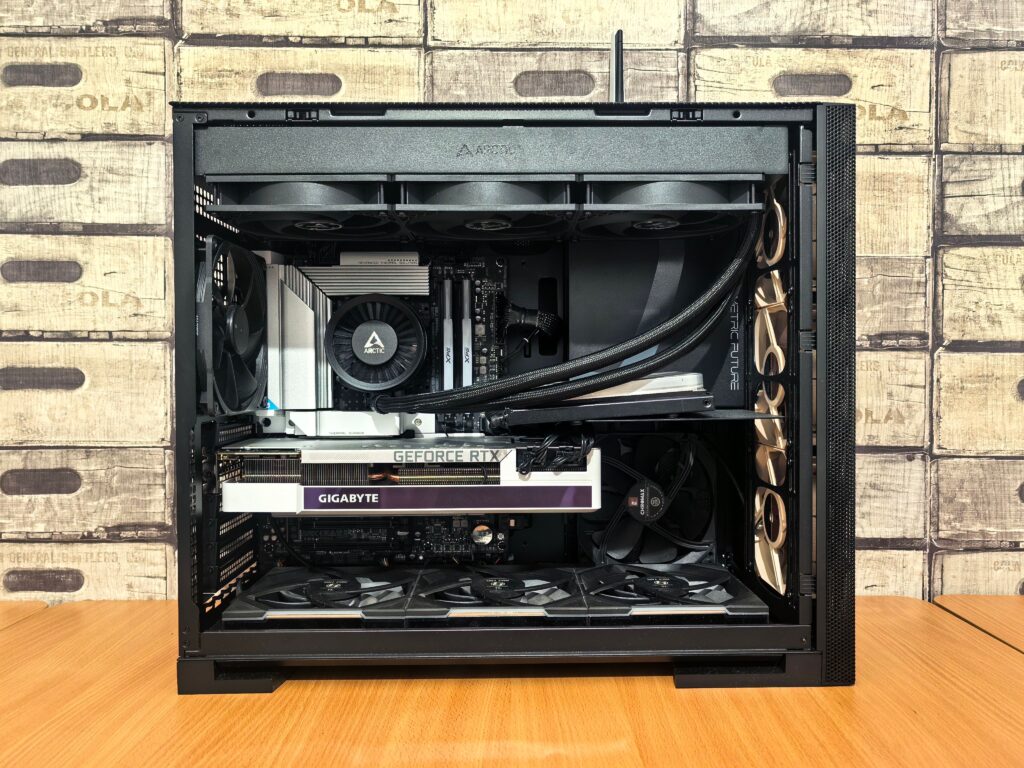
Bad cable management is visible. A tangle of PSU cables blocking the front intake, GPU power cables draped across the motherboard, SATA cables flopping in front of the CPU cooler it’s the difference between a build that looks like a professional assembled it and one that looks like it was finished in a hurry. More than aesthetics, cables in the wrong places restrict airflow, increase temperatures, and make future maintenance significantly harder.
Good cable management isn’t difficult. It requires the right tools, the right order of operations, and understanding where cables actually need to go. This how to cable manage your pc guide covers all of it.
The tools that make it possible
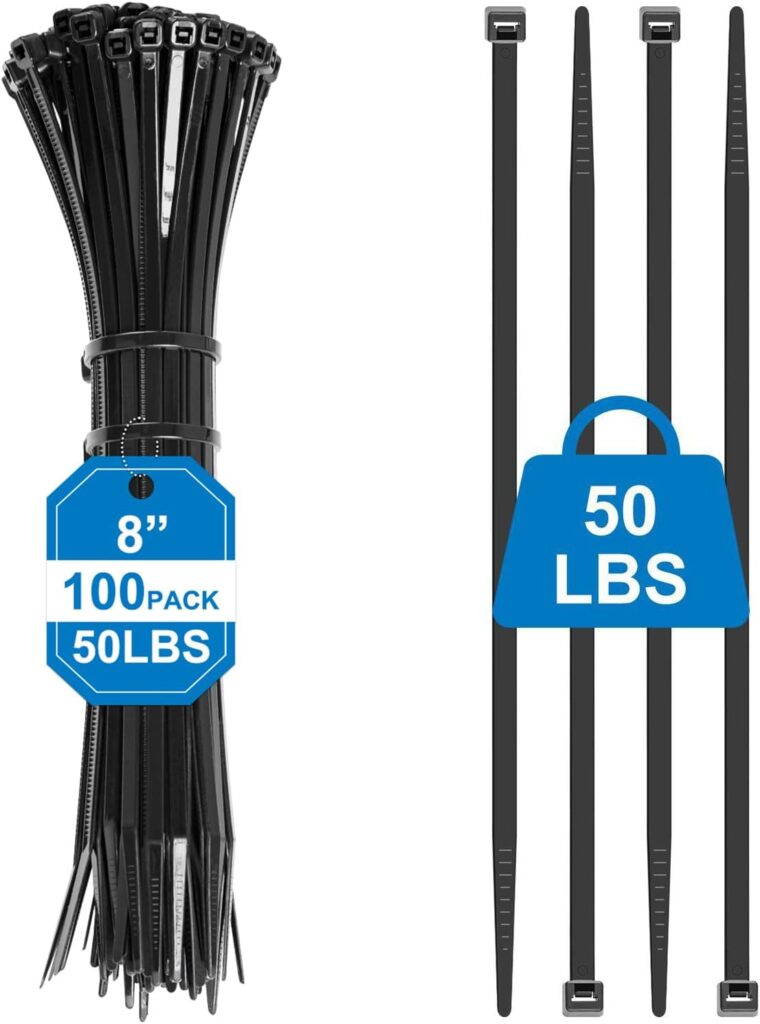
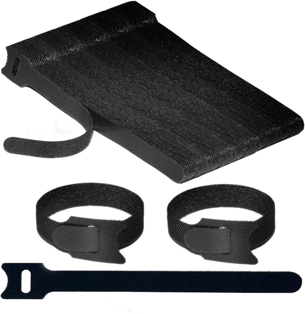
Cable ties are the entry point but not the only tool. Zip ties small plastic loops that ratchet tight are the traditional choice. They work, they’re cheap, and they’re available everywhere. The downside is they require cutting when you need to reroute a cable, which means buying more ties and leaving sharp cut ends that can scratch your hands during maintenance. Velcro cable ties are a better long-term solution reusable, adjustable, and far more hand-friendly. A pack of 100 Velcro ties costs under $10 and handles most builds.
Cable combs small plastic clips that grip around a bundle of parallel cables and hold them in a flat, ordered arrangement are worth buying for the PSU cables that run along the visible side of the case. A 24-pin ATX cable combed into a flat ribbon looks dramatically better than the same cable loosely bundled. Cable combs are sold in sets for a few dollars and clip on without tools.
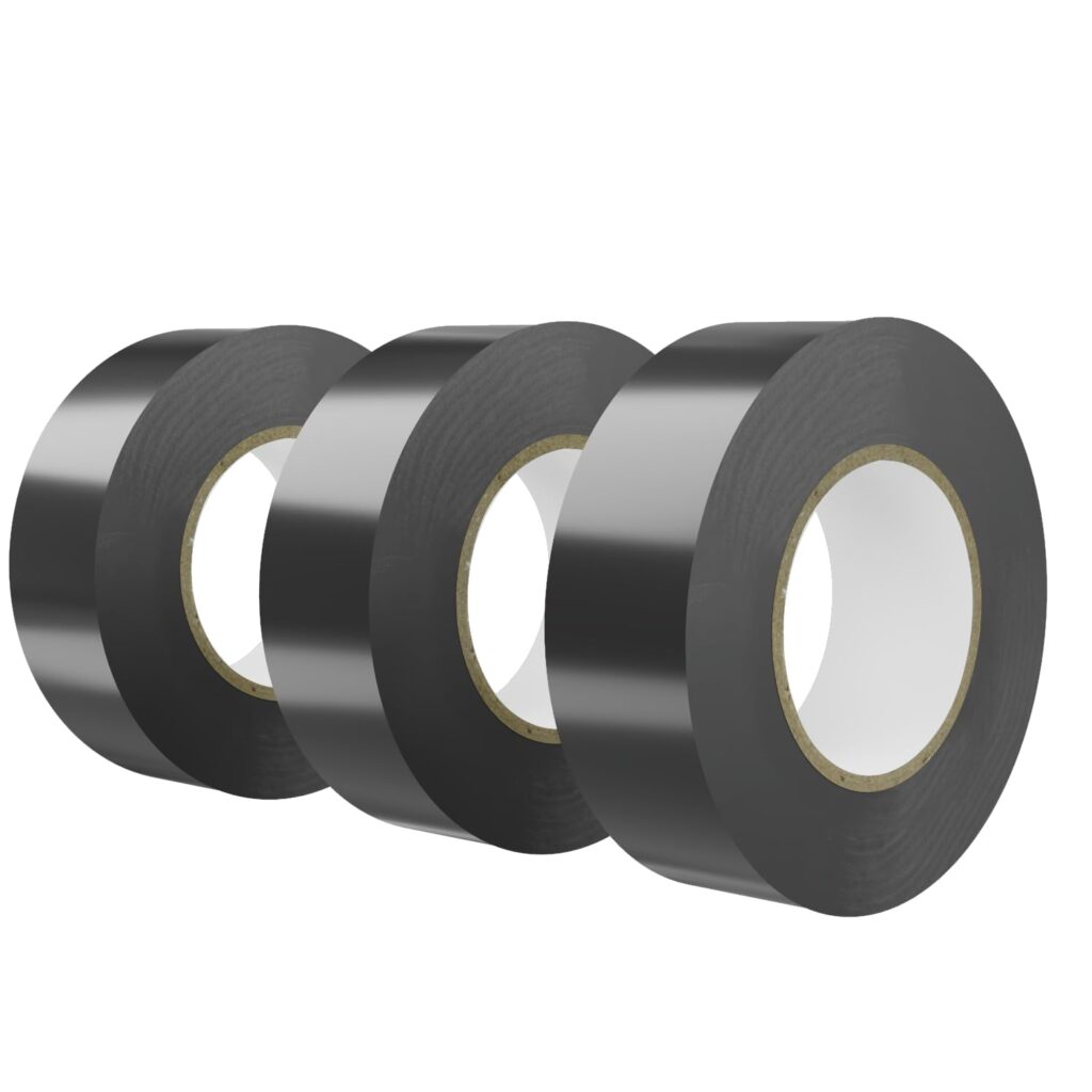
Electrical tape or spiral cable wrap handles awkward lengths that don’t bundle neatly. If you have a cable that’s 100mm too long and creating a loop you can’t eliminate, a few wraps of electrical tape or a short length of spiral wrap tidies it into a manageable shape.
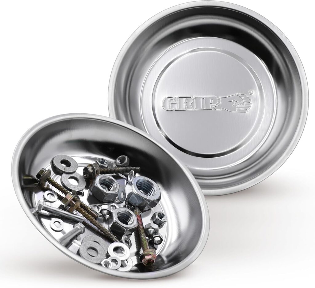
A magnetic parts tray for screws, a phone for photos of cable positions before disconnecting anything, and patience are the remaining tools. The patience is the most important one.
The principle that makes everything else easier
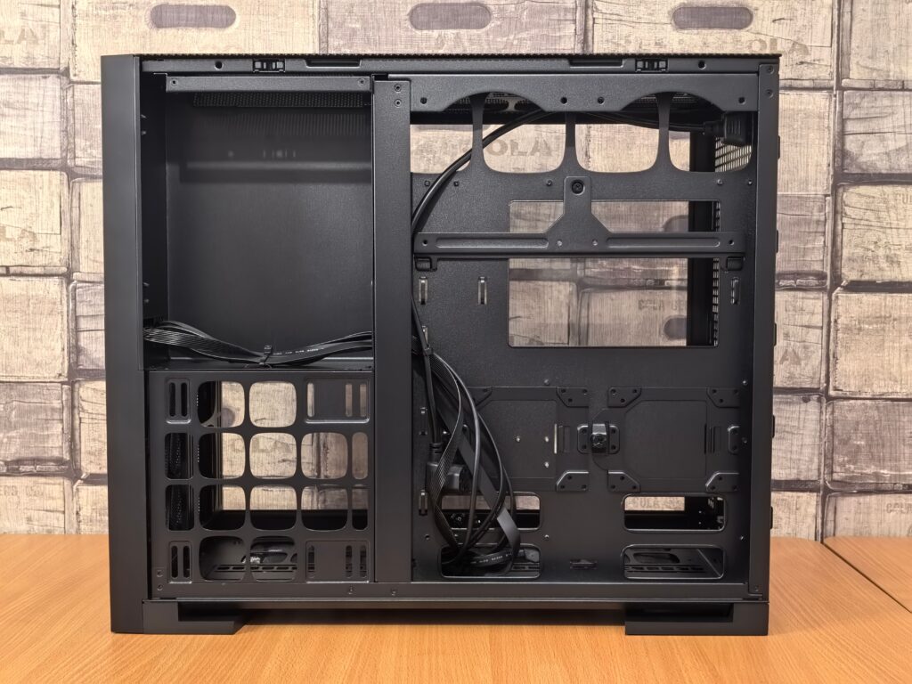
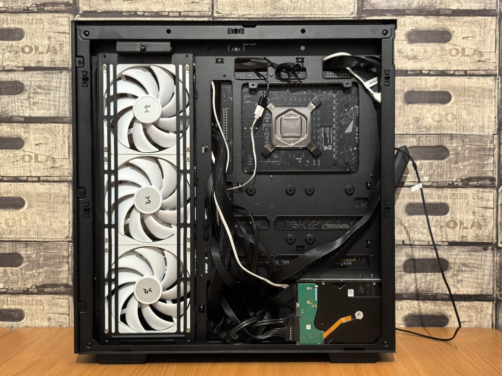
Cables go behind the motherboard tray. Not beside it, not in front of it, not tucked in the corner of the main chamber. Behind it.
Every modern mid-tower case has a gap behind the motherboard tray typically 20–30mm — specifically for cable routing. This space is where the 24-pin ATX cable, the CPU 8-pin cable, SATA data cables, fan headers, and PSU modular cables all live. They enter the main chamber through routing holes cut in the tray, travel the minimum distance to their destination, and connect. Everything else stays hidden.
This is the single most impactful decision in cable management. A build where all cables enter from behind looks completely different from one where cables cross the motherboard or drape in front of fans. Most cases include cable management clips and velcro straps pre-attached in the rear chamber use them.
Step 1 — Plan before you plug in
With the motherboard installed and PSU mounted but nothing else connected, take five minutes to trace the cable path for each connection.
The 24-pin ATX power connector goes to the right side of the motherboard. The cable enters the main chamber from a routing hole on the right side of the tray — usually midway down and travels the shortest path to the 24-pin header. Measure the cable’s approximate path before routing it.
The CPU 8-pin power connector is at the top of the motherboard, often near the top-left corner. The cable enters through a routing hole near the top of the tray or in some cases over the top of the tray and connects directly down. This is the cable most frequently routed incorrectly. It needs to come from behind the top of the tray, not travel up from the PSU through the main chamber.
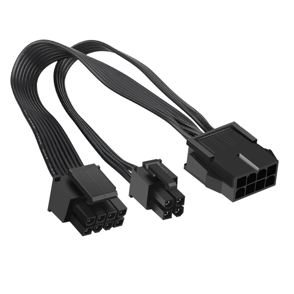
GPU PCIe power cables enter the main chamber from a routing hole near the bottom of the tray, travel up behind the GPU, and connect to the card’s power headers. Modern RTX 50 series cards use the 16-pin 12V-2×6 connector. The cable should approach the GPU from below and behind rather than snaking across the front of the case.
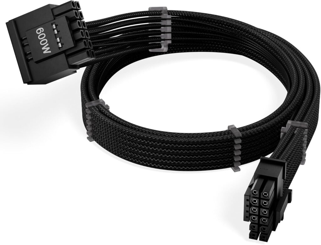
SATA power and data cables are the most flexible to route because drives mount in various positions plan these after the major cables are in place.
Step 2 — Start with the hardest cable first
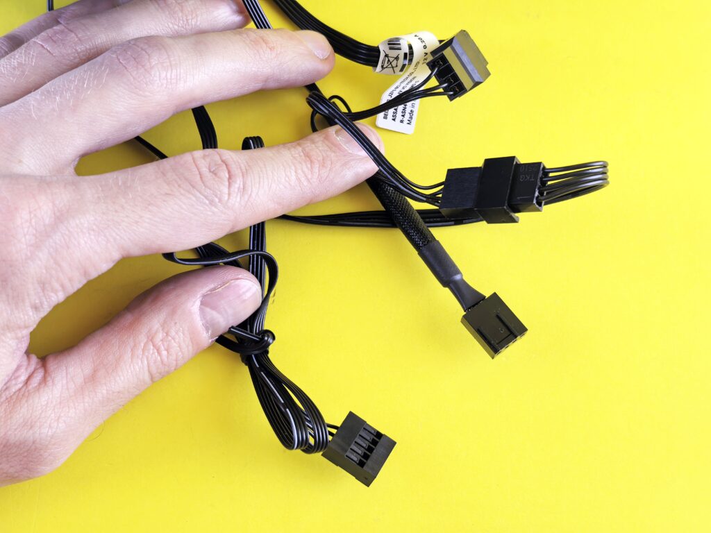
The CPU 8-pin is the most difficult cable to route cleanly in most builds. It has to travel from the PSU at the bottom or rear of the case to the top-left corner of the motherboard. If you route it after other cables are in place, you’ll be fishing it through an already-crowded rear chamber.
Route the CPU 8-pin first. Feed it through the rear chamber from the PSU, run it along the top of the case behind the tray using cable management clips or zip points, and bring it into the main chamber through the routing hole nearest the header. The goal is for it to emerge from behind the tray and travel a few centimetres directly to the CPU power header with no excess cable visible.
Some cases have a dedicated CPU cable routing path that bypasses the rear chamber entirely a channel along the top interior. If your case has one, use it.
Step 3 — Route the 24-pin ATX cable
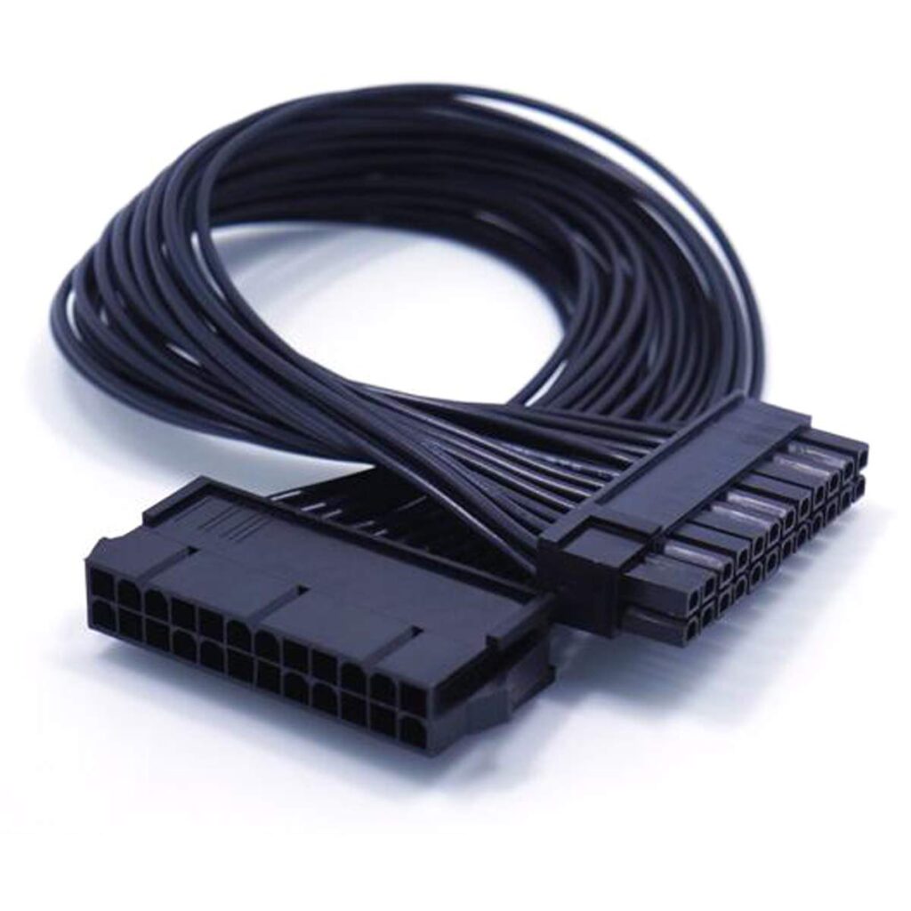
With the CPU cable in place, route the 24-pin ATX cable. It exits the PSU, travels through the rear chamber bundled and secured with velcro ties and enters the main chamber through the routing hole closest to the 24-pin header on the motherboard.
If the cable is too long common with modular PSUs that include cable lengths designed for larger cases fold the excess into the rear chamber. Don’t coil it loosely. Fold it back on itself and use a velcro tie to keep it compact. A folded cable takes up far less rear chamber space than a coil.
Pre-sleeved cables from the PSU or aftermarket cable kits dramatically simplify the 24-pin routing because the cable is already a clean flat ribbon rather than a loose bundle of individual wires. If your PSU came with plain cables and you care about aesthetics, aftermarket cable kits for your PSU model are available from several manufacturers and cost $30–$60 for a full set.
Step 4 — GPU power cables
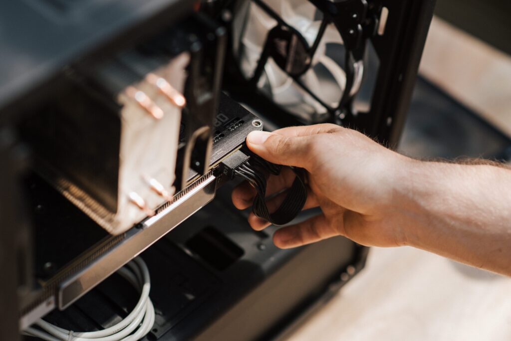
GPU power cables are the most visible cables in most builds they travel from the bottom of the case up to the GPU which sits in the prominent position under the glass panel. Routing them cleanly makes a significant visual difference.
Feed the GPU power cable through the routing hole nearest the bottom of the PCIe area. Bring it up behind the GPU bracket and connect to the card’s power header from below. The cable should travel in a straight vertical line from the routing hole to the connector no loops, no bends, no excess slack visible.
If the cable has too much slack between the routing hole and the GPU connector, fold the excess inside the routing hole or behind the GPU bracket before making the final connection. A taught cable with minimal visible length looks cleaner than a loose cable with any amount of management applied to it.
On RTX 50 series cards with the 16-pin 12V-2×6 connector — make sure the connector is fully seated before routing. A connector that looks connected but isn’t fully latched is both a safety concern and invisible from outside the case once cables are routed.
Step 5 — Fan headers and RGB
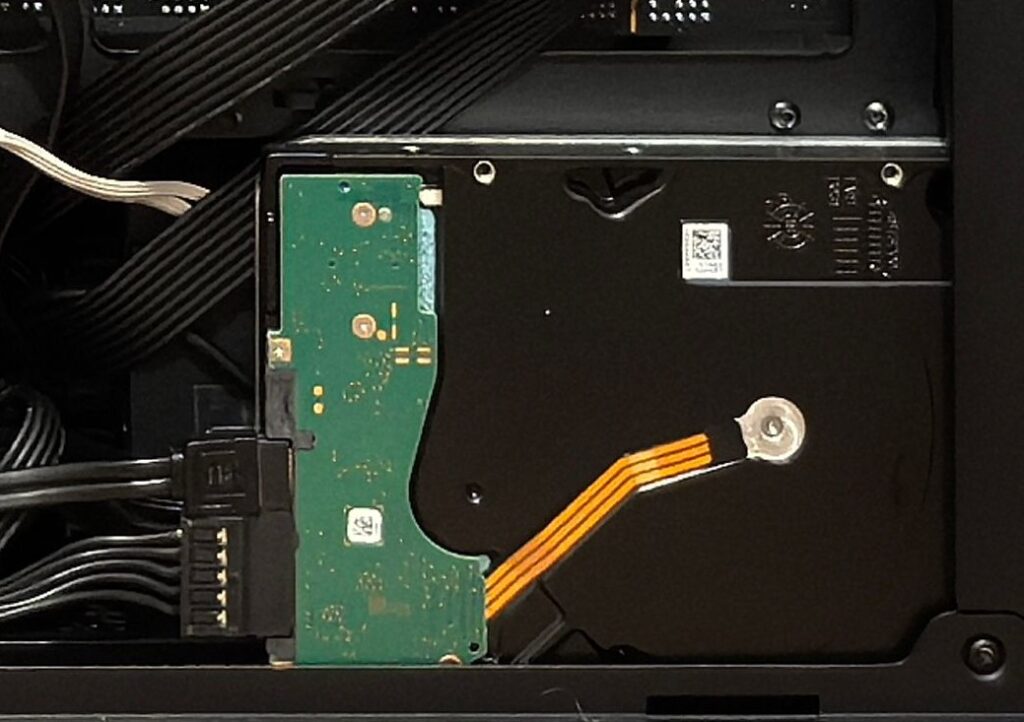
Case fans connect to fan headers on the motherboard or to a fan hub. The cable for each fan needs to travel from the fan’s mounting position to the header with minimal visible excess.
For front intake fans typically mounted at the front of the case the cable naturally routes along the side of the case interior toward the motherboard. Secure it to the case wall using cable management points or small zip ties through fan mounting holes. Don’t let fan cables cross the intake area where they block airflow.
RGB cables follow the same principle. Run them along case walls and behind components rather than across open space. Most RGB cables have enough length to route cleanly if yours don’t, check whether your case has a hub that consolidates connections near the motherboard rather than requiring individual cables to reach across the case.
Step 6 — SATA and storage cables
M.2 NVMe drives have no cables they mount directly to the motherboard. This is one of the significant cable management advantages of current builds compared to SATA-heavy builds from a decade ago.
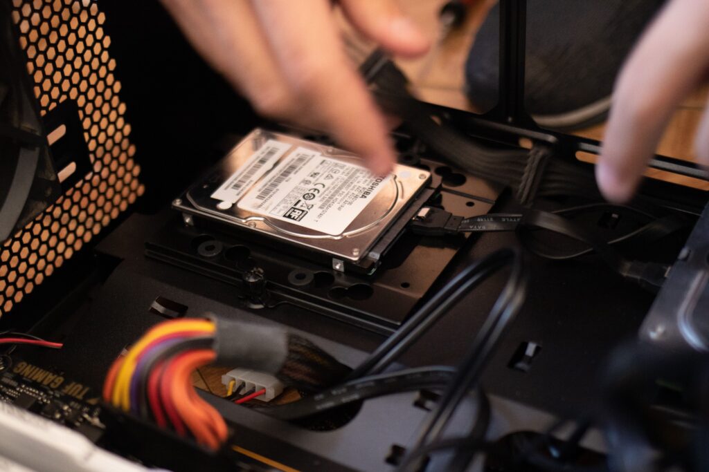
If you’re using SATA SSDs or HDDs, SATA data cables run from the drive bay to the SATA ports on the motherboard. Route them along the floor of the case or through the rear chamber depending on the case design. Right-angle SATA connectors where the connector bends 90 degrees at the drive end — make routing significantly cleaner than straight connectors because the cable exits horizontally rather than vertically from the drive bay.
SATA power cables from the PSU follow the same path as other PSU cables through the rear chamber and entering the main chamber near the drives.
Step 7 — Final tidying and the checks that matter
With all cables routed and connected, take a photo of the main chamber before closing the panel. Compare it against your original mental image or planning notes and check three things.
No cable crosses in front of a fan intake. A cable draped across the front intake reduces the air volume reaching your GPU and CPU. Even a single cable across two-thirds of the intake area is measurable in temperatures. Every cable in the path of an intake fan needs to be rerouted.
No cable is under tension. A cable pulled tight between two points will eventually stress one of its connectors. Every routed cable should have a small amount of slack not loose and looping, but not under tension either.
Every connector is fully seated. The 24-pin ATX, CPU 8-pin, GPU power, and all fan headers need physical confirmation run your finger along each connector and press gently. A connector that clicks when you press it wasn’t fully seated.
Close the rear panel first. Most builds close more easily with rear before side the rear panel’s glass or metal compresses any rear chamber cables and you want to confirm it closes cleanly before committing to the full panel installation.
The back-connect motherboard option — the cleanest builds in 2026
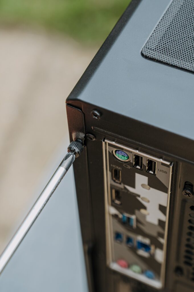
Several motherboards now route all power and data connectors through the back of the PCB the connector exits behind the motherboard tray rather than on the component-facing side. MSI’s Project Zero, ASUS’s BTF, and Gigabyte’s Project Stealth all implement this. The result is a main chamber completely free of cables no 24-pin visible, no CPU 8-pin visible, no fan headers crossing the board. All of it exits behind and routes through the rear chamber entirely.
If a completely cable-free main chamber is the goal, this is the correct platform to build on. Cases designed specifically for back-connect boards including the MSI MPG VIXTA 300R Airflow covered in a previous SpecClear article add specific routing channels for the rear-exit cables.
For standard motherboard builds, the techniques above achieve a clean result. For showcase builds where the cable-free aesthetic is the primary goal, back-connect is the answer.