
Your GPU is running hotter than it used to, you cleaned the fans, cleared the dust from the heatsink fins, and temperatures are still higher than they should be. The next step is repasting replacing the thermal interface material between the GPU die and the heatsink base plate that’s been degrading since the card was built.
It sounds intimidating. It’s not GPU repasting is one of the most impactful maintenance tasks you can do on an older card, regularly dropping temperatures by 10–20°C on cards over two to three years old. This guide covers everything you need before you start including the honest warnings about what varies between cards and where to do your card-specific research before touching a screwdriver.
When repasting is actually worth doing
Not every high GPU temperature is a paste problem, work through this list before opening your card.
Clean the fans and heatsink fins first, dust packed into a GPU heatsink insulates it and raises temperatures by 10–15°C in severe cases. Compressed air through the heatsink from multiple angles takes five minutes and costs nothing. If temperatures drop significantly after cleaning, paste wasn’t the problem.
Check your case airflow a GPU exhausting heat into stagnant case air will run hot regardless of paste quality. Verify you have adequate intake fans and that nothing is blocking the GPU’s own fan intakes.
Monitor the GPU hotspot temperature, not just the average temperature. HWiNFO64 shows both. The average GPU temperature and the GPU hotspot can differ by 20–30°C on modern cards. If your average temperature looks acceptable but you’re throttling, the hotspot is usually the cause and dried paste contributes directly to hotspot increases.
If temperatures are still elevated after cleaning and airflow is correct, and your card is more than two to three years old, repasting is the correct next step. Cards over five years old with original factory paste are almost certain to benefit. If you have not cleaned the card yet, start with our guide on how to clean your PC.
The honest disclaimer about GPU teardowns
This is the part most repasting guides skip. Every GPU model tears down differently. A Sapphire RX 7900 XTX has different screw placement, different fan connector routing, and different backplate attachment than an ASUS ROG Strix RTX 4080. A blower-style card the single-fan designs used in workstation GPUs and some OEM builds disassembles completely differently from a triple-fan open-air consumer card.
What this how to repaste gpu guide covers is the process that’s consistent across most desktop consumer GPUs. The specific screw locations, connector types, and assembly sequence for your card require card-specific research before you start. iFixit, YouTube, and the r/hardware subreddit are the correct resources for your specific model. Search “[your GPU model] teardown” or “[your GPU model] repaste” before picking up a screwdriver. A five-minute video of someone taking apart the same card will save you an hour of confused backtracking.
Tools you need
Quality 90%+ isopropyl alcohol not rubbing alcohol at 70% concentration, which leaves residue. 90% minimum, 99% is better. Available at most pharmacies or online for a few dollars.
Lint-free cloths or coffee filters not paper towels, which shed fibres. Cotton-based cloths work. The lint-free cloths sold for cleaning camera lenses are ideal.
Thermal paste Arctic MX-6, Thermal Grizzly Kryonaut, or Noctua NT-H2 are the standard recommendations. All perform within a degree or two of each other. A single tube costs $8–$14 and is enough for multiple applications. Don’t buy cheap unbranded paste from unknown sources.
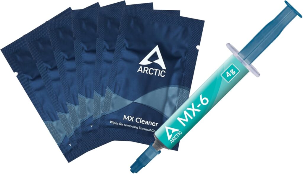
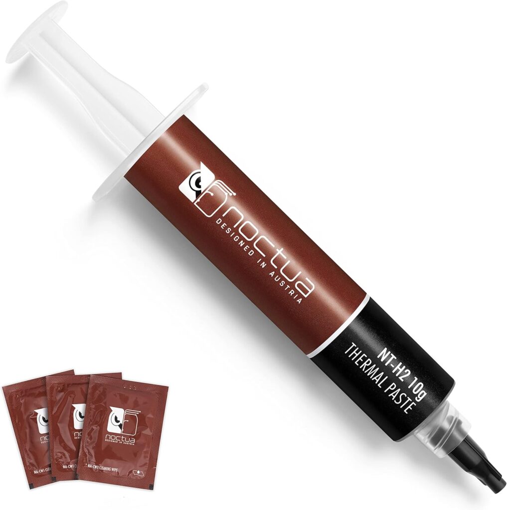
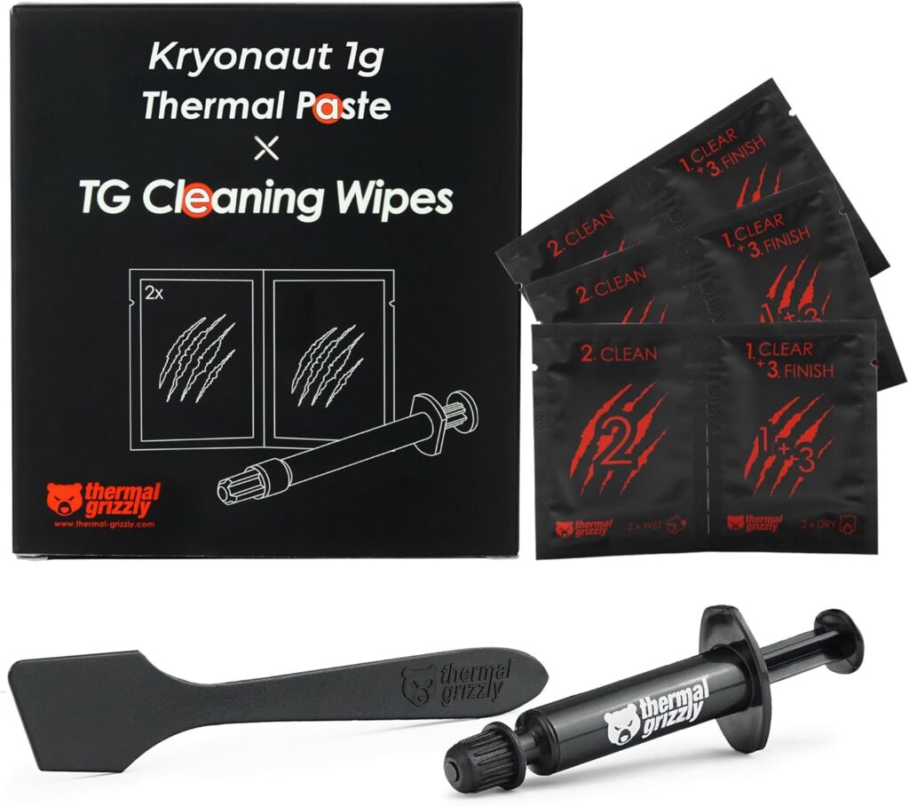
Thermal pads separate from paste, covered in detail below. Don’t skip these.
A precision screwdriver set JIS (Japanese Industrial Standard) screws are common on GPU coolers, particularly on cards manufactured for Asian markets. A JIS #1 and #0 driver prevents cam-out and stripped screw heads. If you only have Phillips drivers, they’ll work on most consumer cards but be careful with small screws. A quality iFixit kit covers JIS and Phillips in the sizes you need.

Plastic spudgers or guitar picks for prying clips without scratching surfaces. Don’t use metal tools to lever open GPU shrouds, metal scratches and can damage PCB traces if it slips.
Anti-static wrist strap optional but recommended, GPU PCBs have surface-mount components that can be damaged by static discharge. Clipping the strap to the metal PC case chassis while working is the correct use.
Tweezers for handling thermal pads and small connectors.
A clean, well-lit workspace ideally a table with a light-coloured surface where dropped screws are visible. A magnetic parts tray keeps screws organised by which part of the card they came from.
Understanding thermal paste vs thermal pads: these are different things
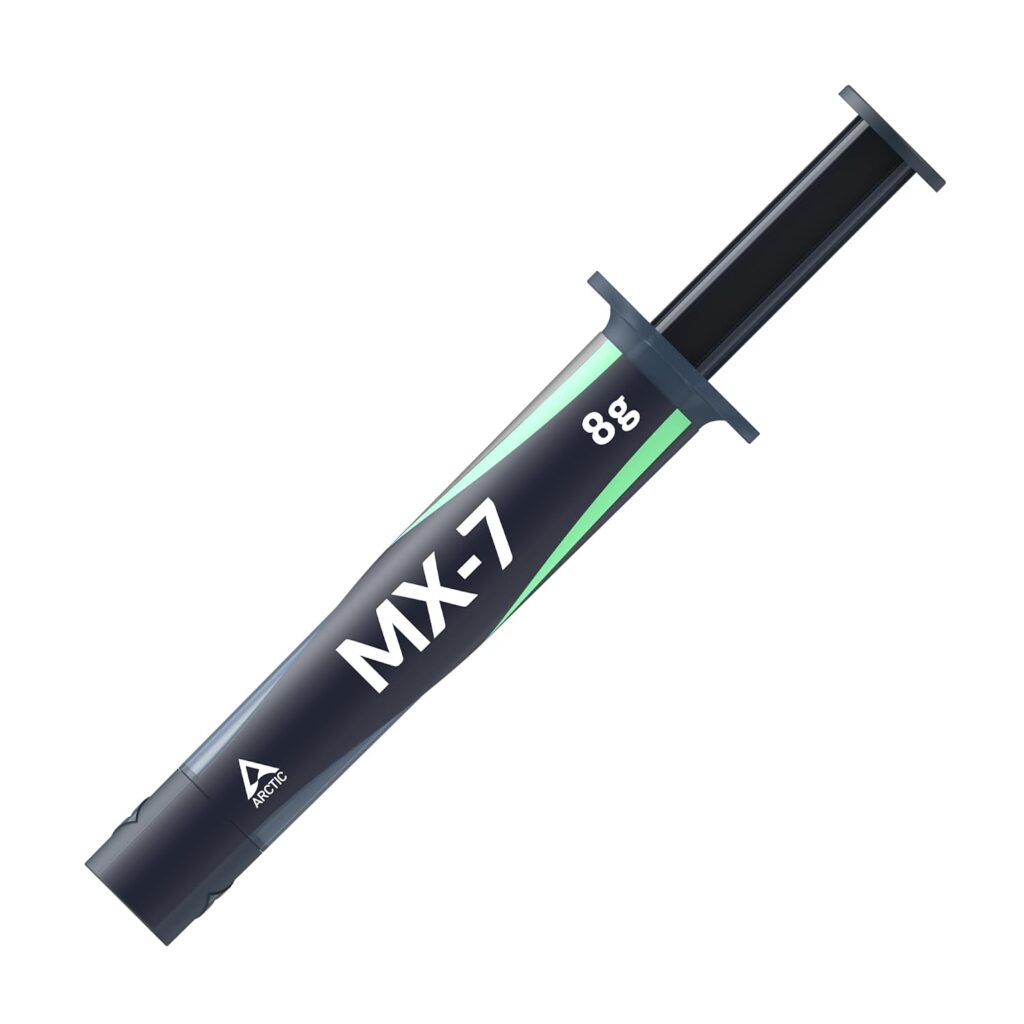
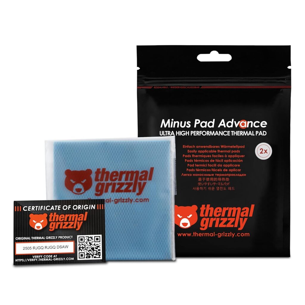
This distinction is the most important technical detail in this entire guide and the one most beginners get wrong.
Thermal paste is the compound that goes between the GPU die the main chip on the PCB and the corresponding contact point on the heatsink base plate directly above it. It fills microscopic surface irregularities and conducts heat from the die into the heatsink. This is what you’re replacing when you repaste a GPU. The die contact area is typically a small square or rectangle in the centre of the PCB.
Thermal pads are solid sheets of thermally conductive material that sit between other PCB components VRAM chips, VRM power delivery components, and sometimes inductors and corresponding contact points on the heatsink. These components also generate heat and need a thermal interface, but the gap between them and the heatsink varies by component height, which is why a compressible pad rather than liquid paste is used.
If you replace the thermal paste but leave dried-out or incorrectly sized thermal pads in place, temperatures may improve on the GPU die but remain elevated on VRAM or VRMs. On cards with 3D stacked VRAM HBM configurations on some professional cards the thermal pad situation is more complex than on standard consumer GPUs with flat GDDR chips.
Thermal pad sizing: the detail that matters most
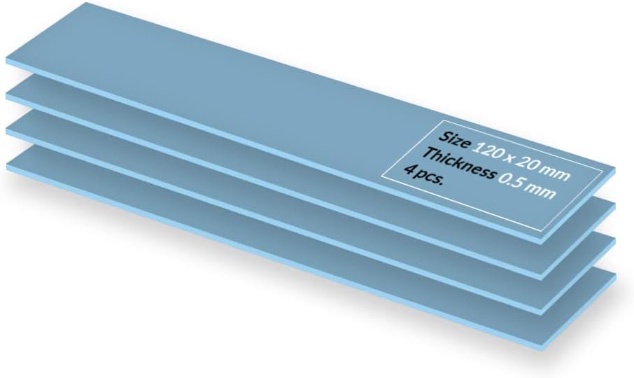
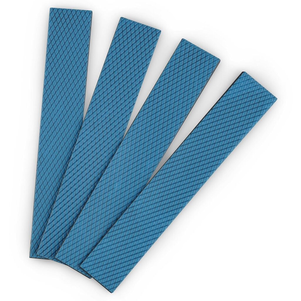
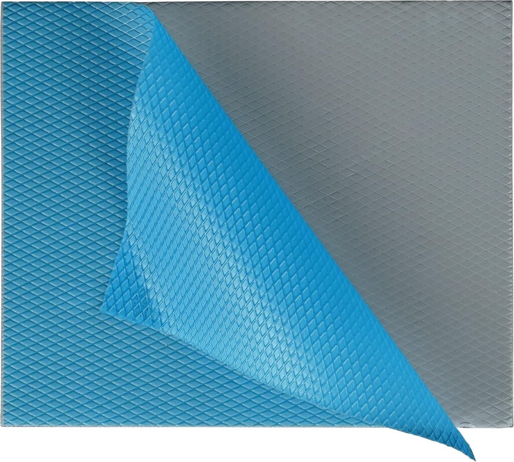
Thermal pads come in different thicknesses and the correct thickness varies by GPU model and component location. Common thicknesses are 0.5mm, 1.0mm, 1.5mm, 2.0mm, and 3.0mm. Putting a 0.5mm pad where a 1.5mm pad belongs means the pad doesn’t bridge the gap between the component and the heatsink you get no thermal contact and the component runs hotter than with no pad at all. Putting a 2.0mm pad where a 1.0mm belongs means excessive compression and possible physical stress on the component.
You cannot determine the correct thickness by looking at a GPU, you need to look it up for your specific card. The r/thermalpad subreddit maintains community-sourced thermal pad specification lists for hundreds of GPU models. GPU teardown videos on YouTube typically call out pad thickness in millimetres when they encounter each component. iFixit teardown guides note pad specifications where documented.
Before ordering any thermal pads, find the pad specifications for your exact card model and board revision. The same GPU model from different AIB partners an MSI RTX 4070 versus an ASUS RTX 4070 may use different pad thicknesses because their PCB layouts and heatsink designs differ.
For the material itself, Thermal Grizzly Minus Pad 8 and Fujipoly XR-m7 are the standard high-quality recommendations. Budget-friendly options like generic silicone pads from Amazon are functional but have lower thermal conductivity. For a high-end GPU where temperatures matter, spend on quality pads a sheet of Thermal Grizzly Minus Pad 8 in the common 100x100mm size costs around $12–$23 and can cover most of a single GPU’s pad requirements.
The general teardown process
Before touching the card: power down completely, switch off the PSU at the rear, unplug from the wall, and press the power button to discharge residual current. Remove the card from the motherboard PCIe slot don’t work on an installed card.
Step 1: Remove the backplate if present
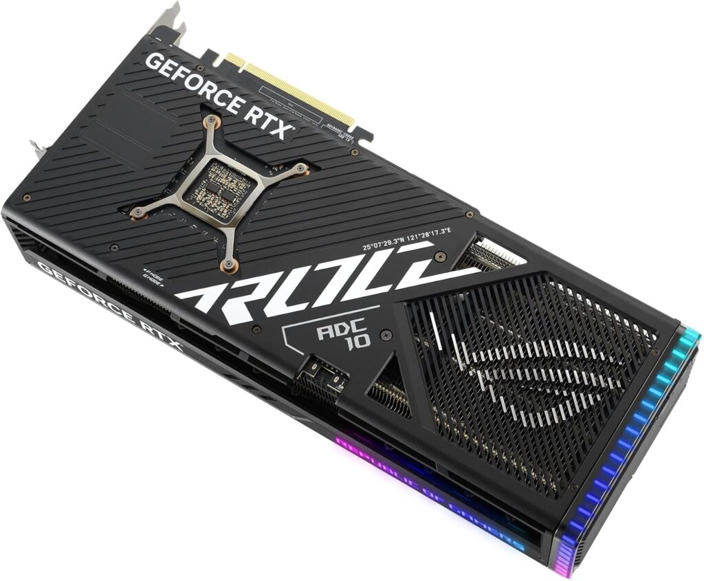
Most modern consumer GPUs have a metal backplate attached by screws through the PCB. These screws are usually visible from the back of the card and often labelled or colour-coded in teardown guides. Remove them in a pattern rather than randomly diagonally opposite pairs first to release pressure evenly. Set the backplate aside with its screws stored separately.
Step 2: Disconnect fan headers
GPU fans connect to the PCB via small headers typically 4-pin connectors on the fan cable that plug into matching headers on the PCB or onto the heatsink bracket. Before removing the cooler assembly, locate and disconnect these. They’re usually on the top edge of the GPU PCB near the fan shroud. Use a spudger or your fingernail to release the locking tab while pulling the connector gently. Never pull by the cable.
On some cards the fan headers are routed through the shroud in a way that makes it difficult to disconnect before the shroud is partially removed. Go slowly and follow a teardown video for your specific model to understand the routing.
Step 3: Remove the heatsink screws
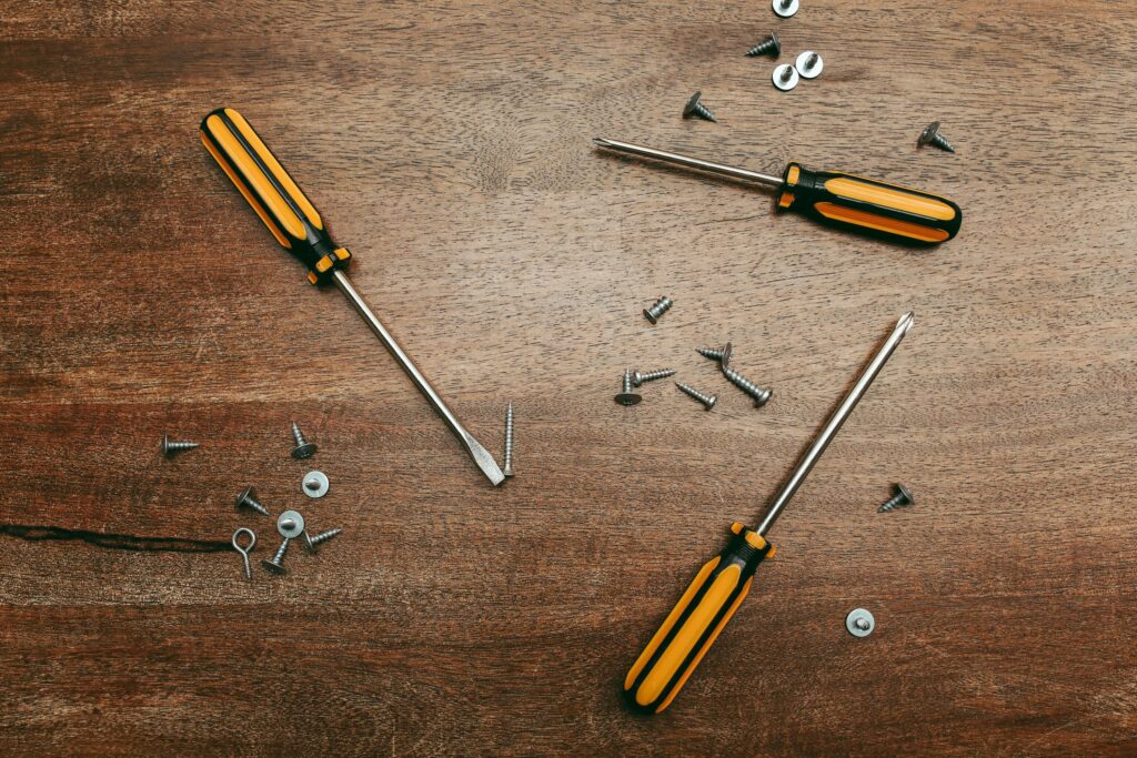
The heatsink is attached to the PCB by screws usually four to eight of them arranged around the GPU die area, with additional screws securing the heatsink bracket across the rest of the PCB. These screws are typically on the component side of the PCB, not the backplate side, and often have spring-loaded washers to apply even mounting pressure.
Remove them in a cross pattern top-left, bottom-right, top-right, bottom-left to release pressure evenly across the die. Some cards have screws of different lengths in different positions. Keep track of which screw came from which hole. A phone photo of the PCB with screws in place before you remove them takes ten seconds and saves significant confusion during reassembly.
Step 4: Remove the heatsink
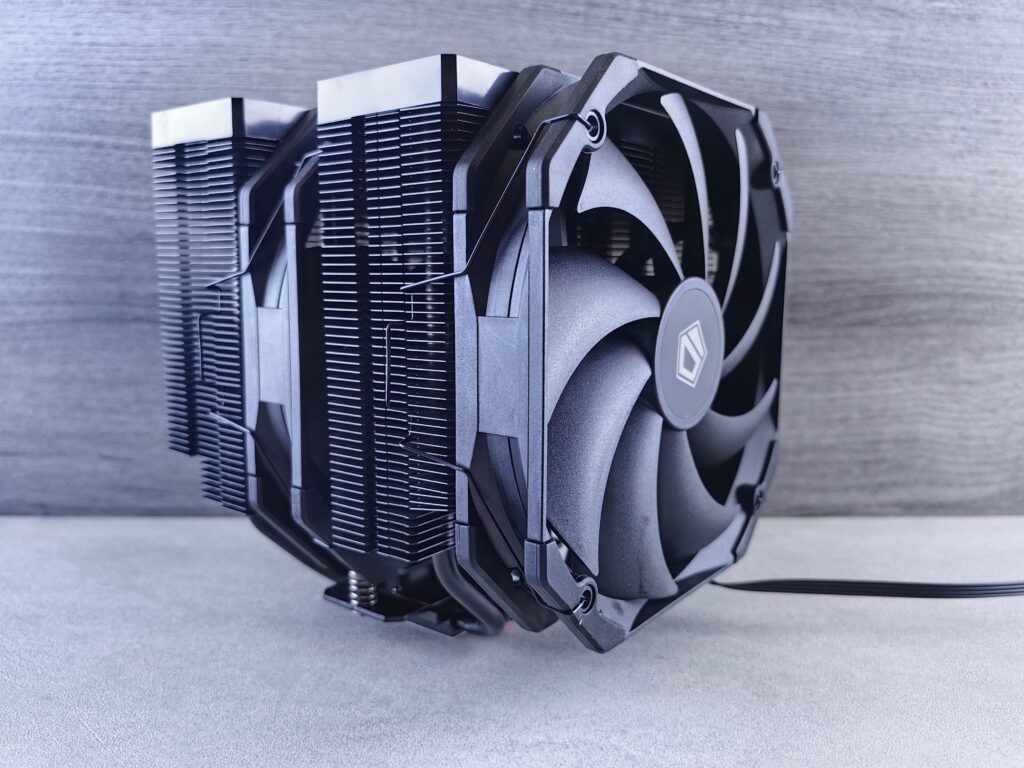
With backplate removed, fans disconnected, and screws out, the heatsink should lift free. It will resist slightly due to the existing thermal paste and pad adhesion. Don’t force it if it’s not lifting, check for a missed screw. Twist gently while lifting to break the paste seal rather than pulling straight up, which risks lifting the GPU die from the PCB on older cards with less robust die attachment.
Some cards have additional adhesive thermal pads that stick firmly to both the PCB component and the heatsink. These will peel slowly as you lift the heatsink. Let them peel naturally rather than yanking.
Step 5: Remove the old thermal paste
The existing paste on the GPU die and the heatsink contact point needs to be fully removed before applying new paste. Apply a small amount of isopropyl alcohol to a lint-free cloth and wipe the die surface in straight strokes rather than circular motions. Repeat until no grey residue remains and the die surface looks clean.
Do the same on the heatsink base plate contact point, isopropyl alcohol evaporates quickly once the surface looks clean and you can’t see any residue, it’s ready.
Don’t use excessive alcohol or let it pool around the die area, a damp cloth rather than a soaking wet one is the correct approach.
Step 6: Remove and replace thermal pads
Peel the old thermal pads from each VRAM chip and VRM component position. Old pads typically peel cleanly but may leave slight residue on either the PCB component or the heatsink surface. A very light wipe with isopropyl alcohol on a cotton tip removes any residue.
Cut your new thermal pads to match the size of each component. Most VRAM chips on modern GPUs are 8mm x 8mm or 10mm x 10mm but measure your specific chips with calipers or match visually to the old pad size. For VRM components and inductors the size varies more cut to fit rather than estimating.
The pad goes on the component side either on the chip surface or on the heatsink contact surface, whichever is cleaner to position on your specific card. Don’t double-pad. One pad bridging the gap from component to heatsink is correct.
Step 7: Apply new thermal paste
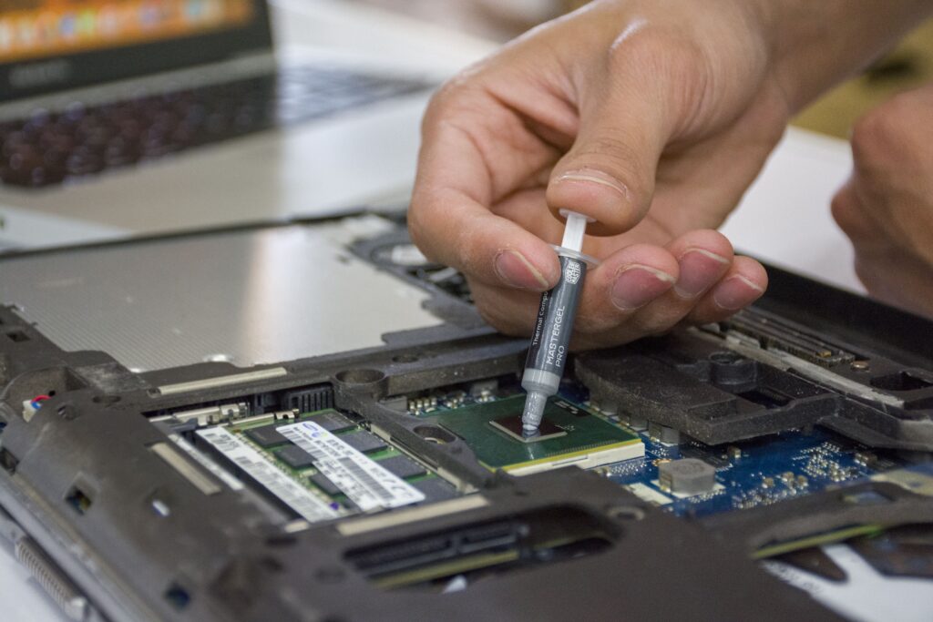
A pea-sized amount in the centre of the GPU die is the correct application. Don’t pre-spread it with a card or finger the mounting pressure from the heatsink screws spreads the paste across the die surface during installation. If you pre-spread you risk air bubbles and uneven coverage.
Some builders prefer an X pattern or a small cross rather than a single dot. All three methods work. The single central dot with pressure spreading is the most forgiving for beginners.
Step 8: Reassemble
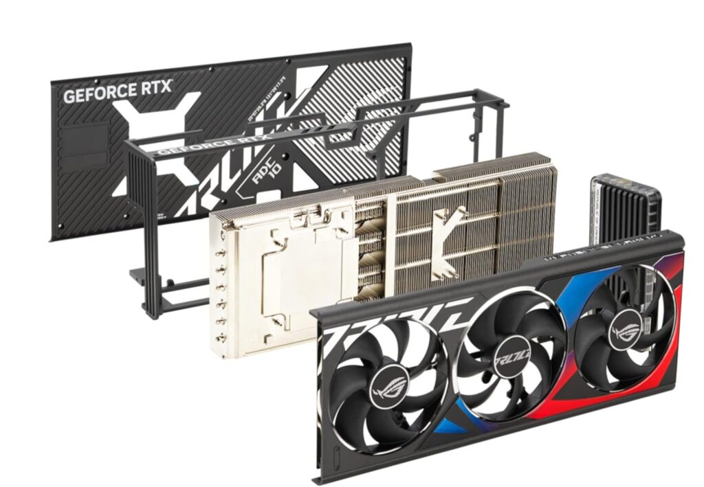
Reconnect fan headers lay the heatsink back onto the PCB with the new paste and pads in place. Hand-tighten the heatsink screws in the same cross pattern used for removal don’t fully tighten one before the others, work around the pattern progressively to apply even pressure. Once all screws are hand-tight, apply final torque equally. Snug-firm is correct. Overtightening can crack the die on older cards with brittle solder.
Replace the backplate screws in the same pattern.
Step 9: Test before reassembling into the case
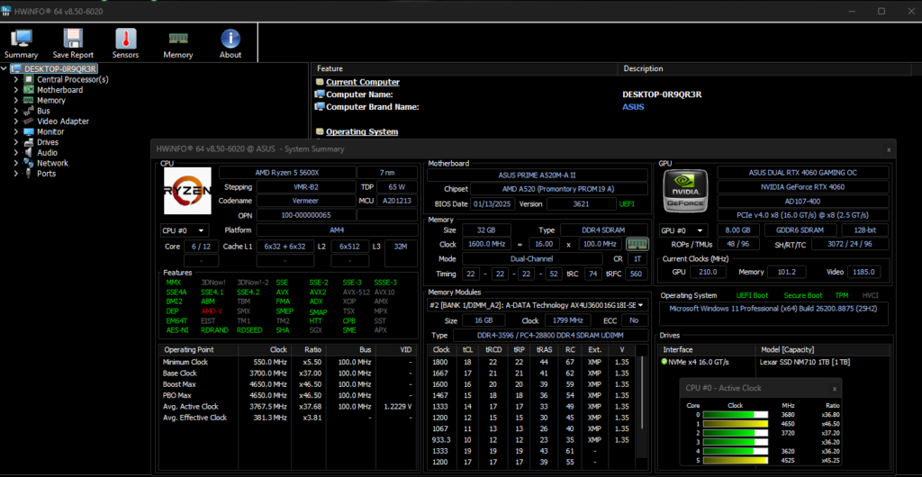
Before reinstalling the card in your PC, connect it externally sit it on a table with power connected via PCIe power cables, plug in a display cable, and boot. If the fans spin and you get a display signal, it’s assembled correctly. Run HWiNFO64 and load the GPU with a game or a stress test for 10–15 minutes. Compare temperatures to your pre-repaste baseline. A 10–20°C drop in GPU junction and hotspot temperatures confirms the repaste was successful.
If temperatures haven’t improved or have gotten worse, the most common causes are: insufficient paste coverage remove the heatsink and check spread coverage on the die, incorrect thermal pad thickness creating poor contact, or a missed screw leaving uneven mounting pressure.
Cards that differ significantly from the process above
Blower-style GPUs single-fan shroud designs common in workstation and server-grade cards typically require removing the entire shroud assembly as one piece before accessing heatsink screws. The fan removal step is different but the heatsink removal, paste replacement, and pad replacement process is the same.
Laptop GPUs are a different category entirely, the disassembly process for laptop GPU repasting varies by laptop model, not GPU model, and typically requires removing the entire laptop base before accessing the cooling system. The paste and pad replacement process is identical but the teardown complexity is significantly higher. If you’re repasting a laptop GPU, find a laptop-specific teardown guide rather than a desktop GPU guide.
Dual-GPU cards historical products from the AMD and Nvidia multi-GPU era have two die contact points and two sets of thermal pads. The process doubles but doesn’t change structurally.
Cards with soldered heatsinks rare on consumer desktop GPUs but present on some compact designs are not user-serviceable. If your heatsink appears to be attached with no visible screws and doesn’t lift after all obvious fasteners are removed, stop and research whether the heatsink design is user-removable before applying force.
After the repaste: what to monitor
Run HWiNFO64 during your first gaming session after repasting. Watch the GPU temperature, GPU hotspot temperature, and VRAM temperature sensors simultaneously. A successful repaste typically shows:
GPU average temperature down 10–20°C versus pre-repaste baseline. GPU hotspot temperature down by a similar or larger margin. VRAM temperature stable or lower if thermal pads were also replaced. Fan speeds lower at equivalent gaming workloads, since the GPU doesn’t need to spin fans as aggressively to maintain safe temperatures.
If VRAM temperatures remain high after repasting the die but replacing the pads, the pad thickness specification may be incorrect for your specific card. Remove the heatsink and check that each pad is making firm contact with both the chip surface and the heatsink contact surface above it.